
Roll tooling is the part of a tube mill that is easiest to buy on price and hardest to fix afterwards. A roll set that is 5% cheaper but designed without checking the flower pattern will cost far more in scrap, setup time and edge wave than the saving.
This is how a roll design is actually developed, in the order the decisions have to be made.
Start with the finished tube, not the mill
The design inputs are: outside diameter, wall thickness, material grade and yield strength, shape (round, square, rectangular, special), tolerance on OD and wall, surface requirement, and the standard the tube must meet. From these come three derived numbers that drive everything:
- Strip width. For round tube the starting point is the neutral-axis circumference, W ≈ π × (OD − t), adjusted for weld upset, edge condition and material.
- t/D ratio. Thin wall (low t/D) buckles easily and needs more support; thick wall needs more bending force and more passes.
- Yield strength. Higher strength means more springback, so the flower pattern must over-bend and the pass count usually rises.
The flower pattern is the design
The flower pattern is a set of cross-sections showing what the strip looks like at every stand. It answers one question: how do we bend this strip from flat to closed without overstraining any part of it?
Good practice:
- Bend the edges early and gently. Edge elongation is what causes edge wave, and edge wave cannot be removed downstream.
- Distribute the total bend angle across all passes. Putting too much angle into one stand creates a kink that shows as a mark on the tube surface and a stress concentration at the weld.
- Keep the strip centred. If the flower drifts left or right, the edges arrive at the weld point out of alignment.
- Leave the last forming passes for alignment, not for bending. The fin passes should be closing an almost-closed section, not doing the heavy work.
Forming method: edge forming, centre forming, or a hybrid
Edge forming bends the strip edges first and works toward the centre; it gives good edge control and is the common choice for tube that will be welded. Centre-out and W-forming distribute strain differently and suit particular size ranges and materials.
The choice affects the number of stands, the roll diameters and how much of the tooling can be shared between sizes. For a mill that changes size often, a design that shares rolls across a size family is worth more than a slightly more elegant flower that needs a full new set for every diameter.
Fin pass: the three millimetres that decide the weld
The fin passes present the two edges to the weld point. Three details matter:
- Edge angle. The edges should arrive at the weld point with the correct V-angle for the HF process, not parallel and not splayed.
- Gap. Too wide and the weld is made across a gap, producing a weak seam; too narrow and the edges touch before the weld point and the current path changes.
- Support. The fin blade has to support the strip close to the weld point without marking it. A worn fin blade is a common cause of a weld that varies around the tube circumference.
This is also where “the roll design is fine but the tube is not” usually lives: the fin pass is set by the operator, not by the drawing, and small setup differences produce large weld differences.
Materials and hardness
Roll material is a wear-versus-toughness decision, not a hardness contest. A roll that is too hard chips at the flange under impact, and a chipped roll marks every tube it touches until somebody notices. The grades below are the ones actually used on ERW mills, in the order buyers ask for them.
| Grade | Equivalent | Where it is used | Hardness after hardening |
|---|---|---|---|
| Cr12MoV | D2 (AISI) / SKD11 (JIS) | Forming and sizing rolls, general duty | 58–62 HRC |
| DC53 | Modified SKD11 | High-speed continuous lines, where fatigue spalling is the failure mode | 60–62 HRC |
| GCr15 | 52100 (AISI) | Small diameter, thin wall, high volume | 58–62 HRC |
| PM high-speed steel | ASP23 class | Long runs on one size, where surface finish of the tube matters | 62–64 HRC |
| Cu-Cr alloy | — | Special cases where heat has to be conducted out of the roll | — |
Two practical notes on that table. Above about ø133 mm we drop the specification to 58–61 HRC: a large section does not harden uniformly, and chasing the last two points of hardness buys wear resistance at the cost of a brittle flange. And GCr15 is not a downgrade — on thin-wall decorative tube it often outlasts D2, because the failure there is polishing wear rather than abrasion.
Heat treatment routes
| Route | Result | When it is worth it |
|---|---|---|
| Vacuum hardening (high-pressure gas quench) + multiple tempering | 61–63 HRC | The default for forming and sizing rolls. Clean surface, minimal distortion, no decarburisation. |
| Vacuum gas quench + sub-zero treatment | 63–65 HRC | Where maximum wear resistance is needed and impact loads are low. Residual austenite is transformed, so the size stays put. |
| Nitriding after hardening (approx. 530 °C, 5 h) | Core 59–61 HRC, hard case | Runs where the groove polishes out before it wears out. The case resists that. |
| Black oxide after hardening | 61–63 HRC | Corrosion protection during shipment and storage more than wear resistance. |
Hardness is only meaningful if it is uniform. A roll reading 60 HRC at the flange and 55 HRC in the groove will wear unevenly and lose its profile even though the certificate says 60. Ask for the hardness map, not the headline number.
The process chain matters more than the grade on the certificate
The order of operations is what separates a roll that holds its pass from one that moves in service. Ours runs: bar stock → sawing → rough turning → drilling → finish turning → groove polishing → marking (size, stand, pass) → semi-finished inspection → heat treatment → bore grinding → keyway broaching → final inspection → cleaning → packing.
Two steps in that chain are the ones buyers should ask about. Stress relief before hardening, because a rolled bar carries residual stress that will move the groove during quenching. And grinding the bore and the groove after hardening, because a roll ground before heat treatment is a roll that changes size afterwards, however good the steel was.
Material source also shows up in service life. Cr12MoV from a mainstream mill and Cr12MoV from a re-rolled billet carry the same name and do not behave the same way; the carbide segregation differs, and segregation is where cracks start. We buy from named mills and can tell you which one a given batch came from.
Sizing and the Turks head
Sizing rolls correct OD and ovality after welding. Their design follows from the sizing sequence: how many stands, how much reduction per stand, and whether a Turks head is used for straightness and for square/rectangular sections. Over-sizing — using sizing to fix a forming error — shortens roll life and produces residual stress.
What to send a roll supplier
- Tube drawing with OD, wall and tolerance.
- Material grade and yield strength.
- Mill make, model, stand count and shaft diameter.
- Existing roll drawings or samples, if any.
- Strip width you actually buy, not the theoretical one.
- Production volume and changeover frequency.
The fifth point is the one buyers skip. If your strip arrives 1 mm wider than the theoretical width, the roll design must be made for the strip you have, not the strip in the textbook.
Our roll tooling section covers forming, fin, sizing and weld rolls, and the roll design page explains how we handle flower patterns for non-standard sections.
Frequently asked questions
What is a flower pattern in tube mill roll design?
A flower pattern is the series of cross-sections showing how the flat strip is progressively bent at each forming stand. It is the core of roll design because it determines bend distribution, edge strain and whether the edges arrive at the weld point correctly aligned.
How is strip width calculated for round tube?
The starting point is the neutral-axis circumference, approximately π × (OD − wall thickness). The final width includes allowances for weld upset, edge condition and material behaviour, and is normally confirmed on the first trial run.
How many forming passes does a tube mill need?
It depends on diameter, wall thickness, material strength and the forming method. Thin-wall small tube may need 6–8 forming stands; thick-wall or high-strength tube needs more passes to distribute strain and avoid edge wave.
Keep reading

Tube Mill Roll Changeover: Where the Hours Actually Go
Ask a mill manager how long a size change takes and the answer is usually a number with a shrug:…

Reading Roll Wear: Resharpen, Recoat or Replace?
Every roll set reaches a point where the decision is no longer technical but economic. Four measurements tell you whether…
Roll Material and Heat Treatment: D2, Cr12MoV, GCr15 and What Actually Lasts
Two roll sets can look identical and last very differently. The difference is in the steel grade, the heat treatment…
Related Products
Machines that do the job described above — quoted station by station.
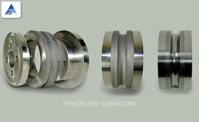 ProductTube Mill Rolls & Roll ToolingPass design, machining and vacuum hardening in-house.View specifications →
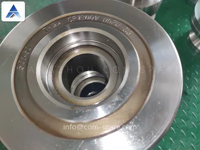 ProductTube Mill RollsFinished passes, ground after hardening.View specifications →
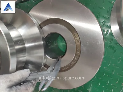 ProductTube Mill MouldForming and sizing moulds to your flower pattern.View specifications →
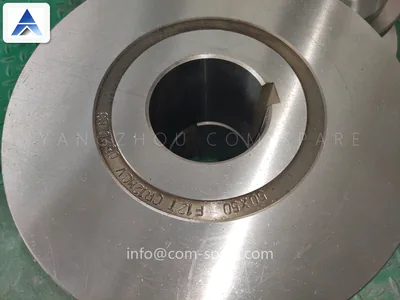 ProductTube Mill Roll SetA complete pass line, numbered and pre-set.View specifications →
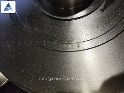 ProductTube Mill Roll DesignFrom flower pattern to finished pass drawing.View specifications →
Need this checked on your own mill?
Send tube OD, wall thickness and the symptom. We reply within one working day.