
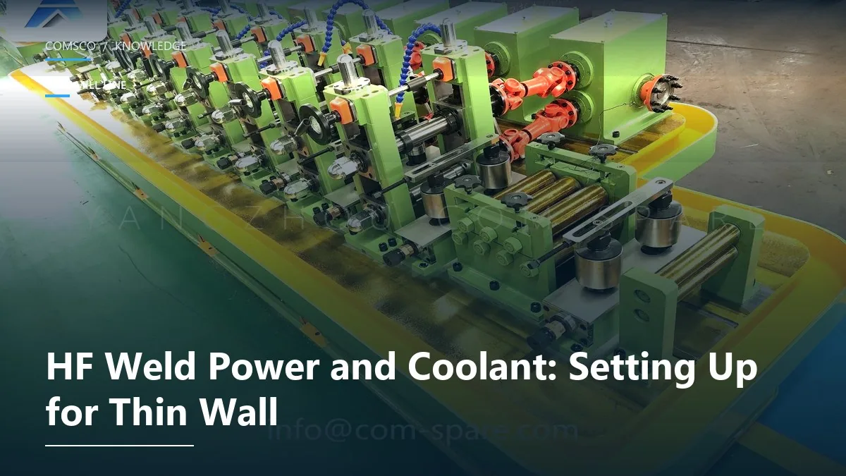
Thin wall is where a tube mill stops being a forming machine and starts being a heat balance. Below about 1.2 mm the strip has very little thermal mass, travels fast, and loses heat to the rolls on both sides. The window between “not fused” and “burnt through” is narrow, and it moves every time line speed changes.
This is not a power setting problem, although it is usually treated as one. Power is one of five variables, and it is rarely the one that should be moved first.
What thin wall changes
| Variable | Thick wall behaviour | Thin wall behaviour |
|---|---|---|
| Heat input needed | High | Low, and falls fast with speed |
| Time in the weld zone | Long enough to stabilise | Short; the seam is in and out |
| Heat loss to rolls | Small relative to input | Large relative to input |
| Effect of a 10% speed change | Small | Visible on the next tube |
| Failure mode | Lack of fusion | Burn-through, or fusion that looks fine and fails on expansion |
The last row is the one that hurts. A thin-wall seam can pass a visual check, pass a flatten test on a short sample, and still open up when the tube is expanded or bent, because the heat-affected zone was too wide and the grain structure never recovered.
Frequency and coupling
Solid-state HF welders on tube mills typically run 200 to 400 kHz. Higher frequency concentrates the current nearer the surface, which is helpful on thin wall — but only if the contact or induction coil is set correctly, because a badly coupled coil at 400 kHz behaves worse than a well-set one at 250 kHz.
- Contact welders put current into the strip through sliding contacts. Contact pressure, contact condition and distance from the weld point all affect coupling. A worn contact is a power loss that shows up as an unstable seam.
- Induction welders couple through a coil around the tube. Coil diameter, position and the gap to the strip matter more than the power setting.
On either type, check coupling before touching the power dial. A mill that has started needing 15% more power than it did last month is telling you about contact wear or coil position, not about the steel.
The impeder: the most under-checked part on the mill
The impeder sits inside the tube at the weld point. Its job is to increase the impedance of the current path so that the current prefers the strip edges rather than short-circuiting around the inside of the tube.
An impeder that is too small, too far from the weld point, or waterlogged will let current bypass the seam. The operator sees a cold weld and adds power; the extra power goes into heating the whole tube instead of the edges.
| Impeder check | Accept | Symptom if wrong |
|---|---|---|
| Position relative to weld point | Per mill drawing, typically just behind the weld | Seam cold at correct power; tube body hot |
| Diameter vs tube ID | Close fit without rubbing | Current bypass, low efficiency |
| Cooling water flow | Steady, no air bubbles | Impeder overheats, performance drifts over a shift |
| Core condition | No cracks, no rust bridging | Erratic weld quality that comes and goes |
A five-minute impeder check at the start of a shift prevents most of the power-chasing that happens later in it.
V angle and squeeze
The strip edges meet at a V. The angle of that V and the amount of squeeze at the weld point decide how much of the heated edge is forged together.
- A V that is too open wastes heat into the strip faces and produces a wide, weak heat-affected zone.
- A V that is too closed forces the edges to touch before they are hot enough, and the result is a cold joint with a heavy outside bead.
- Squeeze too low gives a seam with insufficient forging; too high gives a heavy internal and external bead, which then loads the scarfing tool.
On thin wall, set the fin passes so the edges arrive at the weld point touching lightly, then adjust squeeze in small steps while watching the bead. The bead is the feedback: a bead that is even and small means the heat and the squeeze are matched.
Cooling: inside, outside, and the emulsion
Thin wall needs cooling close to the weld, but cooling too close steals heat from the seam. The usual arrangement is external coolant just after the weld and internal coolant through the impeder, with the flow set so the tube is cool enough to size without quenching the seam before it has forged.
Emulsion concentration is the variable that quietly changes everything else. A mix that has drifted rich cools better but leaves residue that burns on the weld; one that has drifted lean cools worse and rusts the mill. Check concentration weekly, not when a problem appears.
A setting order that works
- Strip and forming. Confirm strip width, edge condition and that the fin passes are delivering a consistent V. Nothing downstream compensates for a bad V.
- Impeder. Position, fit and cooling.
- Coupling. Contact condition or coil position.
- Squeeze. Set so the edges meet with light contact at the weld point.
- Speed. Set the line speed you actually intend to run. Do not tune at a speed you will not use.
- Power. Raise from low until the bead forms evenly. Stop at the first point where the seam is fully fused; more power is not more safety.
Tuning in that order means power is the last thing changed and the first thing you can trust. Tuning in the reverse order — power first, then everything else — is how a mill ends up running 20% hotter than it needs to, with a heat-affected zone to match.
What good looks like on thin wall
- Bead narrow and even on both sides, with no scalloping.
- No heat tint spreading more than a few millimetres from the seam.
- Flatten test opens the seam without separating — the fracture runs through parent metal, not along the weld line.
- Tube body still cool enough to handle a metre behind the weld.
If the tube is hot a metre behind the weld, the power is going into the tube rather than the seam, and the answer is usually coupling or impeder, not a lower power setting.
Related reading: What each of the nine stations decides and Strip edge quality before the mill.
Keep reading
Why a Tube Mill Loses Size After the First Hour — and Where to Look First
OD is correct at start-up, then creeps out of tolerance as the mill warms up. Nine times out of ten…
Specifying a Tube Mill Line: Ten Numbers to Bring to the First Meeting
Most first quotations are wrong because the buyer sends a diameter range and nothing else. These ten numbers let a…
ERW Tube Mill Line: What Each of the Nine Stations Actually Decides
A station-by-station walk through an ERW tube mill line — what each unit controls, which tolerances it owns, and where…
Related Products
Machines that do the job described above — quoted station by station.
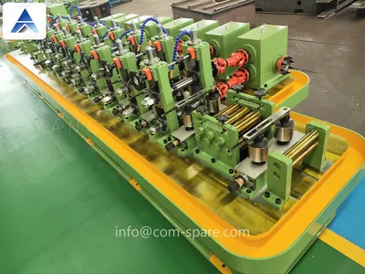 ProductERW Tube Mill LineComplete ERW lines from coil to bundle, Φ8–355 mm.View specifications →
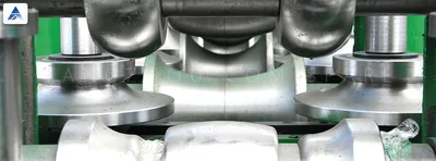 ProductERW Tube MillForming, welding, sizing and cut-off as one pass line.View specifications →
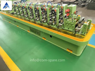 ProductHF Tube MillSolid-state welders sized to your heaviest wall.View specifications →
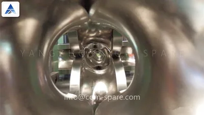 ProductSteel Tube MillStrip width, wall and grade decide the whole layout.View specifications →
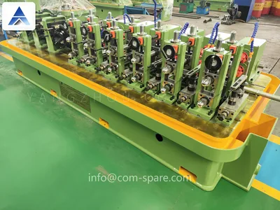 ProductAutopacking MachineCount, stack and strap finished tubes.View specifications →
Need this checked on your own mill?
Send tube OD, wall thickness and the symptom. We reply within one working day.