
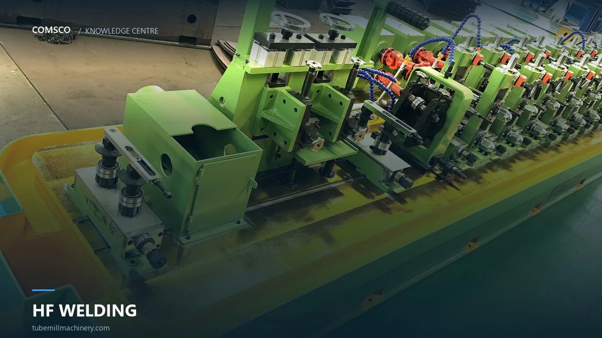
Part of our tube mill line guide.
In high-frequency ERW welding, the impeder is the part inside the tube that controls where the welding current flows. It is easy to overlook because it sits out of sight, but its condition and position decide how much of the HF energy goes into the two strip edges instead of into the rest of the tube. When a weld becomes inconsistent and the power setting has not changed, the impeder is one of the first things worth checking.
What the impeder actually does
HF welding current follows the path of lowest impedance. The impeder — a core made from magnetic ferrite material, carried on a water-cooled support — sits inside the formed tube close to the weld point. Its presence raises the impedance of the current path around the inside of the tube, which pushes the current to concentrate at the strip edges and the V gap. The result is localized heating at the edges, so the tube reaches welding temperature without heating the whole circumference. Without it, more energy is needed, the heat-affected zone widens and the weld becomes less stable.
Core, support and cooling
An impeder assembly has two parts that wear differently. The ferrite core is the working element: it is brittle, and it can crack or erode if it is knocked against the inside of the tube or run without adequate cooling. The support and its water cooling keep the core in position and carry away the heat it absorbs. On a production line the core is a consumable — it is replaced on a schedule, not only when it fails — because a chipped or shortened core changes the current path before it fails completely.
Placement is as important as the core
Three placement details matter more than the grade of ferrite. First, the impeder should sit as close to the weld point as the stand geometry allows; moving it away lets the current spread and reduces edge heating. Second, it must be centred in the tube — a core that rides against one side pulls the heat pattern off the weld seam. Third, the working length inside the tube has to suit the tube diameter and the speed. Too short and it does not shape the path enough; too long and it adds drag and heat without adding weld quality.
Selecting an impeder for thin-wall tube
Thin-wall tube is where selection is most critical, because the heat-input window is narrow. Too much energy and the edge burns through; too little and the seam never reaches forging temperature. For thin wall, a correctly sized core close to the weld point lets you run with lower total power and a tighter heat pattern. The core diameter follows the inside of the tube, and the length and position are set against the mill speed and the wall thickness you actually run. Rather than quoting a universal size, we ask for the tube OD, wall, line speed and the stand layout, then confirm the setting on the first trial.
Common signs of an impeder problem
- Weld that varies around the circumference or drifts during a shift with no change in power
- Need to keep increasing HF power to hold the same weld
- A wider-than-normal heat-affected zone or burn-through on thin wall
- Water temperature or flow at the impeder support changing from the normal pattern
Any of these is a reason to stop and inspect the core and its position before changing the welding recipe. A cracked or eroded core is cheap to replace; the scrap from chasing the fault through power settings is not.
Impeder and guide tooling are different parts
It is worth separating two things that are often confused. The impeder described here is a process component for HF welding, located inside the tube at the weld point. The mechanical guide parts in the roll tooling section — the pieces that set the strip path between stands — do a different job and are selected against the pass line drawing. If your problem is strip wandering rather than weld heat, the guide tooling is where to look. For help with either, send the tube size and a description of the symptom and we will tell you which part is responsible.
Frequently asked questions
Is the impeder a consumable?
Yes. The ferrite core wears and can crack, and it is replaced on a schedule in production. The support and cooling assembly normally last longer than the core.
Why is my weld inconsistent even with stable HF power?
Check the impeder first: its position, centring and core condition all change the current path without any change in the power setting.
Can one impeder size cover all tube diameters?
No. The core diameter and working length follow the tube inside diameter and the wall thickness. Size it from the product you actually run.
Keep reading
ERW Weld Seam Defects: A Diagnostic Order That Saves Time
By Deffy Su, in this trade since 2011 · COMSCO engineering notes · Last reviewed November 2026 Part of our…
HF Weld Power and Coolant: Setting Up for Thin Wall
By Deffy Su, in this trade since 2011 · COMSCO engineering notes · Last reviewed November 2026 Part of our…
Tube Mill Roll Changeover: Where the Hours Actually Go
By Deffy Su, in this trade since 2011 · COMSCO engineering notes · Last reviewed November 2026 Part of our…
Strip Edge Quality Before the Mill: Slitting, Burr and Weld Defects
Half the weld defects blamed on the welder are decided before the strip reaches the first stand. Edge burr, camber…
Accumulator Sizing: How Many Seconds of Strip Your Line Really Needs
An undersized accumulator turns every coil change into a mill stop. Here is the calculation, the three accumulator types, and…
Shear & End Welder: The Coil Joint That Decides Your Weld Seam
The joint made at the entry section passes through every forming stand and arrives at the weld point. If defects…
Related Products
Machines that do the job described above — quoted station by station.
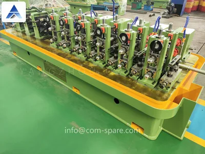
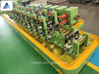 ProductERW Tube Mill LineComplete ERW lines from coil to bundle, Φ8–355 mm.View specifications →
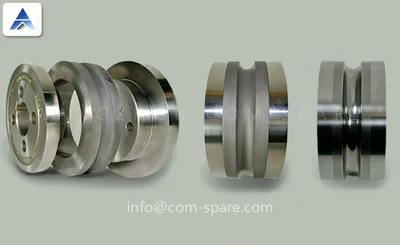
 ProductAutopacking MachineCount, stack and strap finished tubes.View specifications →
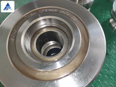
 ProductTube Mill Rolls & Roll ToolingPass design, machining and vacuum hardening in-house.View specifications →
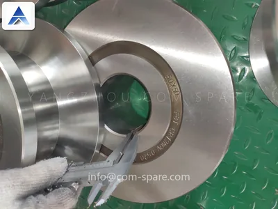
 ProductTube Mill RollsFinished passes, ground after hardening.View specifications →
 ProductTube Mill MouldForming and sizing moulds to your flower pattern.View specifications →
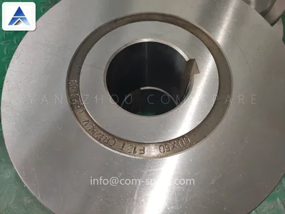 ProductTube Mill Roll SetA complete pass line, numbered and pre-set.View specifications →
 ProductTube Mill Roll DesignFrom flower pattern to finished pass drawing.View specifications →
Need this checked on your own mill?
Send tube OD, wall thickness and the symptom. We reply within one working day.